These are some of the Circuit Diagrams and Logic Gate Work we did in class.
|
|
|
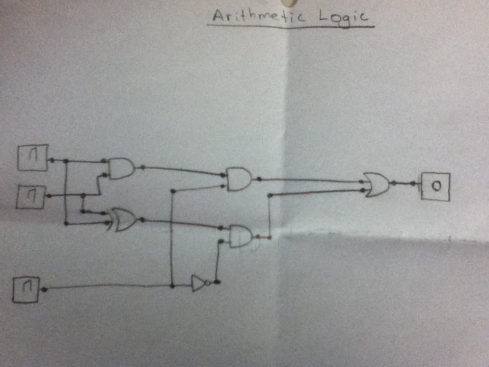
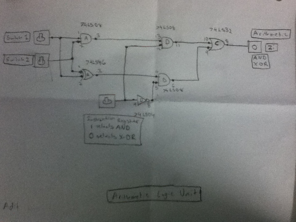
On the left is the diagram of an Arithmetic Logic unit. According to the switch position the circuit acts as an X-OR or an AND gate and the corresponding outcome is outputted by the LED |
|

|
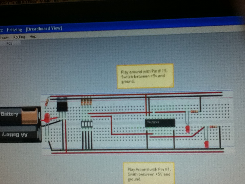
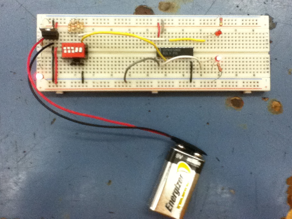
Above are two circuits we made while working with NPN and PNP Transistors.
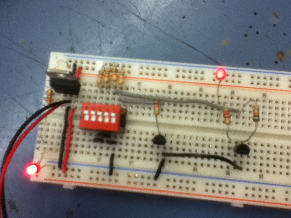
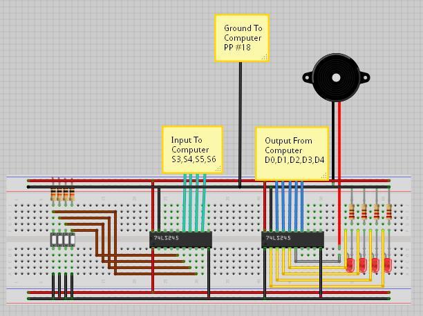
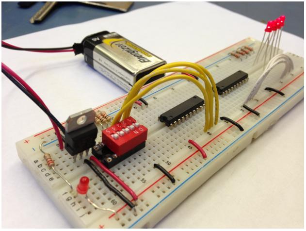
Below is a diagram of a circuit we had to build with a buffer chip and the final product.
|
|
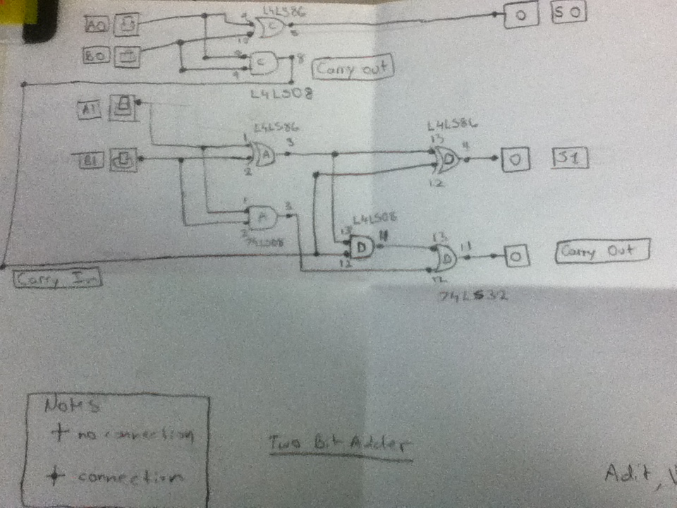
This is our final summative assignment:
|
|
